Views: 0 Author: Site Editor Publish Time: 2026-06-24 Origin: Site
In commercial HVAC and refrigeration, unequal refrigerant distribution leads to starved coil circuits, localized icing, and compromised system capacity. Engineers constantly battle these inefficiencies when designing high-performance cooling networks. Poor fluid division ruins even the best evaporator coils. Heat transfer relies heavily on homogeneous fluid delivery across every available circuit. Selecting the proper distribution hardware is a critical engineering decision. It directly impacts the efficiency of the expansion valve. It also determines the overall heat transfer rate of the fan coil unit (FCU). Precise matching prevents serious performance bottlenecks.
This guide provides a straightforward, engineering-focused framework for evaluating, sizing, and specifying these components. You will learn how to accurately calculate pressure drops and select the optimal nozzle. We also cover essential installation techniques. By following these guidelines, you ensure balanced flow and long-term system reliability.
The core objective is straightforward. You must ensure equal division of the two-phase refrigerant mixture leaving the thermostatic expansion valve (TXV). This mixture contains dense liquid and light flash gas. If they separate prematurely, some circuits flood while others starve. A starved circuit absorbs very little heat. A flooded circuit risks sending liquid back to the compressor. You must keep the liquid and gas completely mixed until they enter the evaporator tubes.
The cost of poor specification is remarkably high. Mismatched or improperly sized components lead to hunting TXVs. The valve constantly opens and closes as it searches for a stable superheat reading. This instability reduces compressor lifespan significantly. It also yields poor sensible heat ratios. The system simply struggles to remove heat effectively. You waste energy and increase wear on mechanical parts.
Positioned directly between the expansion valve and the evaporator coil, this component acts as the critical refrigerant liquid distributor. It dictates total coil efficiency. You cannot treat its selection as an afterthought. Precision engineering at this junction guarantees optimal heat exchange. It ensures every square inch of the evaporator coil does its share of the cooling work.
Evaluate the required pressure drop across the device and its internal nozzle. Usually, this falls between 15 to 35 psi. The exact number depends heavily on the specific refrigerant and the target application. You cannot size based on nominal tonnage alone. Nominal ratings assume standard conditions. Actual field conditions vary wildly.
Assess component performance at partial load conditions. Refrigerant velocity must remain high enough to prevent gas and liquid separation. Low loads often cause sluggish flow. Sluggish flow lets gravity pull the liquid downward. Proper sizing guarantees mixed-phase delivery even when the system operates at low capacity.
| Refrigerant Type | Application Type | Target Pressure Drop Range (psi) |
|---|---|---|
| R-410A | Air Conditioning | 25 - 35 |
| R-134a | Medium Temp Refrigeration | 15 - 25 |
| R-404A / R-448A | Low Temp Commercial | 20 - 30 |
Match the outlet count exactly to the number of circuits in the heat exchanger distributor coil. A strict rule of thumb exists in HVAC engineering. Never plug unused distributor outlets. Doing so disrupts the internal flow geometry immediately. It causes uneven fluid division across the remaining active ports. If your coil has six individual circuits, you must purchase a six-circuit model.
Attempting to cap off an extra port alters internal fluid dynamics. The mixture will favor certain pathways over others. This completely defeats the purpose of the component. Always map your coil geometry before ordering parts.
Specify the correct outer diameter (O.D.) for the outlet tubes. They must match the evaporator coil connections flawlessly. Standard O.D. sizes range from 3/16 inch to 5/16 inch for commercial applications. Accurate sizing maintains appropriate refrigerant velocity through the connection lines.
This velocity is absolutely necessary to carry oil back to the compressor. Compressors rely on returning refrigerant to bring lubricating oil home. Sluggish oil return ruins compressors over time. Proper tube sizing keeps the mixture moving fast enough to suspend the oil droplets.
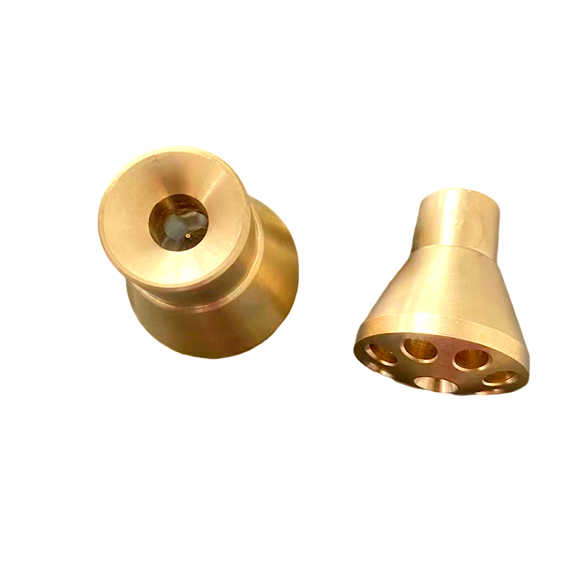
Function over form is the guiding principle here. The nozzle acts as a precision orifice to increase fluid velocity. It homogenizes the liquid and flash gas before the mixture hits the dispersion cone. Without a nozzle, the fluid enters too slowly. It separates into distinct vapor and liquid streams. The nozzle forces them to mix violently.
Consider the differences between interchangeable and fixed nozzles before specifying a unit.
Use strict sizing logic when selecting the orifice diameter. Base the nozzle size on the specific refrigerant you intend to use. Factor in the design evaporating temperature. Always include the exact liquid temperature entering the TXV. Changes in liquid subcooling drastically affect the required nozzle diameter. Rely on manufacturer sizing charts rather than estimation.
Why should you specify brass? Highlight the significant metallurgical advantages of a brass distributor. It provides exceptional corrosion resistance against moisture. It offers excellent machinability, allowing for incredibly precise internal cones. Furthermore, it boasts superb thermal stability. Brass handles rapid temperature fluctuations without warping or fracturing over time.
Brazing realities matter greatly in the field. Integrating brass components into existing systems is simple. You can easily connect them to standard copper fan coil unit fittings. Technicians use standard silver brazing alloys for these joints. Ensure you clean the mating surfaces thoroughly first. Apply adequate flux to achieve deep capillary action.
Verify pressure ratings and modern refrigerants. The brass alloy and wall thickness must comply with strict safety standards. Check for UL or ASHRAE 15 compliance. Modern systems utilize high-pressure A2L refrigerants. These fluids demand robust containment vessels. A properly forged brass body easily withstands operating pressures exceeding 650 psig.
| Material Characteristic | High-Grade Brass | Standard Copper |
|---|---|---|
| Machinability (Internal Cones) | Excellent | Fair |
| Burst Pressure Resistance | Very High | High |
| Brazing Compatibility | Excellent with silver alloy | Native |
Orientation requirements are notoriously strict. You must mount distributors vertically. They can point directly up or directly down. This vertical stance prevents gravity from separating the liquid and vapor phases. Horizontal mounting is a primary cause of system failure. Gravity drags the heavy liquid down. Consequently, horizontal units send only gas to the upper coil circuits.
Tube length equivalence is entirely mandatory. We must reiterate the necessity of identical lengths. All connecting tubes must share the same physical length. They must also share the same bend radii. Unequal lengths create unequal pressure drops. Fluid always follows the path of least resistance. Shorter tubes will steal the majority of the refrigerant.
TXV proximity is another crucial installation factor. Mount the unit as close to the expansion valve as physically possible.
Extra distance allows premature separation of the two-phase mixture. Keep the physical connection short, direct, and completely unobstructed.
Follow a methodical, engineering-driven process when specifying parts. Bypassing these steps leads to erratic system behavior.
We strongly recommend using a high-quality brass liquid distributor to ensure optimal longevity. Meticulous specification upfront prevents catastrophic field failures later. It protects the compressor and guarantees the end user receives the cooling capacity they purchased.
Choosing the right distribution hardware is an exercise in precision engineering. It requires strict alignment between system capacity, pressure drop, and physical geometry. Never treat this component as an optional accessory. It serves as the primary controller of your entire evaporator efficiency. Proper selection ensures your cooling coils perform exactly as engineered.
Prioritize manufacturers that provide transparent sizing charts. Look for companies offering interchangeable nozzle options. Demand verifiable pressure ratings that handle modern, high-pressure refrigerants. Finally, double-check field installation protocols meticulously. Always ensure your theoretical design translates seamlessly to actual performance in the field.
A: No. Plugging unused outlets disrupts the internal flow dynamics immediately. This disruption leads to severely uneven fluid distribution across the remaining ports. Always specify a distributor with the exact number of required outlets to match your coil geometry.
A: The fundamental fluid physics remain the same. However, commercial refrigeration units handle different refrigerants and much wider temperature deltas. A standard air conditioner distributor focuses on typical comfort cooling. Refrigeration models require specific nozzle sizing adapted for ultra-low-temperature applications.
A: Yes. The TXV only controls the superheat. The distributor nozzle is strictly required to create the high velocity needed. This velocity mixes the flash gas and liquid, ensuring equal distribution into the multiple evaporator circuits.
A: Remove any interchangeable internal nozzles or retainer rings before applying the torch. Wrap a wet rag around the main body to act as a heat sink. Always purge the lines with dry nitrogen while brazing to prevent internal oxidation.
