Views: 0 Author: Site Editor Publish Time: 2026-05-25 Origin: Site
Refrigerant branch piping plays a critical role in modern VRF and VRV systems. While piping components represent a remarkably small fraction of total HVAC project expenses, they carry immense operational weight. Standardizing on the correct components dictates overall system longevity, compressor health, and peak energy efficiency.
Many installers treat branch selectors as basic commodities, which introduces massive system vulnerabilities. Subpar fittings lead directly to uneven temperature distribution across building zones. Furthermore, improper branch selection causes catastrophic refrigerant leaks and immediately voids OEM warranties. You cannot afford to compromise on these critical junctions.
This guide serves as a technical, decision-stage framework for HVAC engineers, contractors, and procurement managers. We will explore how to evaluate, size, and select the correct branch fittings. You will learn the physics behind refrigerant distribution and discover expert strategies to bulletproof your next installation.
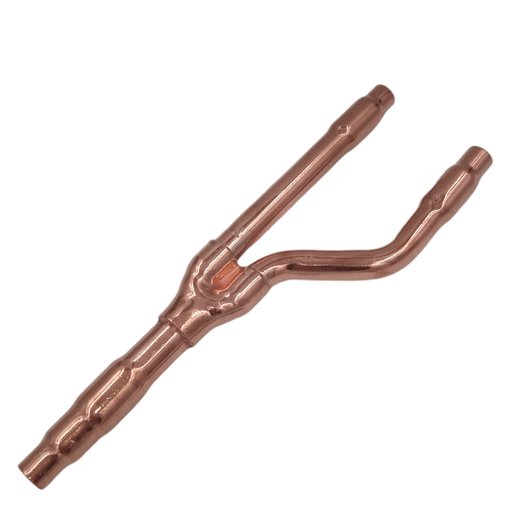
Refrigerant flow within a VRF system behaves differently than basic water plumbing. Modern systems utilize two-phase flow, meaning liquid and vapor travel through the lines simultaneously. A specialized copper Y branch pipe is meticulously engineered to separate these liquid and gas lines precisely. The unique Y-shaped geometry ensures uniform refrigerant distribution to multiple indoor units from a single outdoor condenser. When fluid enters the joint, the shape allows it to split proportionally without disrupting the delicate liquid-to-vapor ratio.
You cannot use a standard plumbing tee as an air conditioner branch pipe. Standard copper tees force high-velocity refrigerant to smash into a flat wall and split at a harsh 90-degree angle. This violent change in direction destroys laminar flow. It creates severe turbulence inside the pipe. Because vapor is lighter than liquid, the turbulence forces vapor down one path and liquid down the other. Consequently, some indoor units starve for refrigerant while others flood. This imbalance ultimately sends unevaporated liquid back to the compressor, causing fatal mechanical failure.
Utilizing purpose-built VRF branch joints delivers significant operational advantages:
Selecting the right components requires strict adherence to metallurgical standards. You must specify premium-grade, deoxidized copper for all system branches. Most top-tier manufacturers utilize C1220 or SF-Cu alloys. We must also differentiate between copper temper grades based on system requirements. O-type (annealed soft copper) offers flexibility for smaller diameters, making it easier to handle. Conversely, 1/2H-type (half-hard copper) provides the rigid structural integrity needed for larger diameter pipes handling immense internal forces.
Modern low-GWP refrigerants like R410A and R32 operate at substantially higher pressures than legacy refrigerants. Your piping infrastructure must accommodate these extreme conditions. When evaluating a VRF copper refnet joint, look for minimum working pressure ratings exceeding 50 bar (approximately 725 psi). Elite manufacturers push these boundaries even further during factory testing. Acceptable benchmarks include sustaining 4.17MPa for leak holding and surviving up to 12.51MPa for ultimate burst pressure.
| Performance Metric | Standard Requirement | Elite Factory Benchmark |
|---|---|---|
| Working Pressure Rating | > 3.0 MPa | > 5.0 MPa (approx. 50 bar / 725 psi) |
| Leak Holding Pressure | 3.5 MPa | 4.17 MPa |
| Ultimate Burst Pressure | 10.0 MPa | 12.51 MPa |
Strict manufacturing quality assurance separates premium fittings from dangerous counterfeits. Instruct buyers to mandate seamless extrusion processes. Seamless construction eliminates weak weld points where high-pressure leaks typically originate. Furthermore, demand 100% inline eddy current flaw detection. This electromagnetic testing process identifies microscopic wall thickness variations and invisible hairline cracks. Finally, ensure manufacturers utilize an acid-free manufacturing environment. Acid residues left inside the pipe eventually react with refrigerants, causing devastating internal corrosion.
Sizing branch piping requires strict mathematical mapping. You must never guess pipe dimensions based on visual diameter. Instead, rely on the Capacity Index Logic. Manufacturers assign a Capacity Index Number or Tonnage (TR) value to every indoor and outdoor unit. You determine the appropriate distribution coupling size by summing the capacity index of all downstream indoor units connected to that specific branch.
Deviating from the manufacturer's specific sizing charts invites severe mechanical failure.
Commercial installations frequently feature exceptionally large indoor units, often rated at 72 or 96 MBH. Connecting these massive air handlers requires specialized techniques. Designers must utilize specific "twinning joints" to merge multiple ports safely. Twinning allows the system to deliver the immense refrigerant volume required without violating pipe velocity constraints or compromising phase separation.
Contractors typically employ two primary methods to connect a copper refnet joint to the main system network. Each approach carries distinct procedural requirements and risk factors.
Brazing remains the industry gold standard for VRF connections. It creates a permanent, metallurgically bonded seal capable of withstanding decades of thermal expansion and contraction. However, technicians must strictly follow the nitrogen purging protocol. Heating copper in the presence of ambient oxygen creates cupric oxide inside the pipe. We commonly call this "scale." This abrasive black debris eventually flakes off, circulates through the system, and permanently clogs the micro-orifices of Electronic Expansion Valves (EEVs). Purging low-pressure nitrogen through the pipes during brazing completely prevents oxidation.
Modern alternatives like ZoomLock and LOKRING offer cold connection solutions using specialized hydraulic press tools. These mechanical fittings grip the copper tubing and form a tight, O-ring-backed seal.
Pros: Cold pressing completely eliminates hot work permits, fire watches, and the risk of internal oxidation. In environments like active hospitals or historic wooden buildings, this proves invaluable. It can also reduce labor costs by 40% to 60%.
Cons: The primary drawback involves upfront tooling costs. Hydraulic press jaws represent a significant investment. Additionally, press tools require specific spatial clearances. Technicians often struggle to fit these bulky tools into tight ceiling voids or densely packed utility shafts.
Even the highest-quality components fail if installed incorrectly. Fluid dynamics require strict adherence to geometric constraints. Installers must prioritize precise spatial orientation to ensure equal phase distribution across the network.
When installing a joint horizontally, you must monitor the tilt angle carefully. The branch must never exceed a 30° tilt from the level plane. Exceeding this angle causes gravity to pull liquid refrigerant into the lower branch while sending vapor to the upper branch. This destroys system balance. Conversely, you can install the joint vertically, pointing either straight up or straight down. However, twisting or bowing the vertical assembly is strictly prohibited.
Refrigerant needs physical space to calm down after passing through a fitting. We refer to this as the straight pipe buffer. Installers must maintain mandatory distances to preserve laminar flow. Always leave a minimum of 12 inches (approximately 30cm) of completely straight pipe between two separate branch joints. You must apply this same 12-inch rule between a joint and any 90-degree elbow. Furthermore, maintain a minimum of 500mm straight pipe clearance before the line enters the indoor unit.
Refrigerant lines operate at extreme temperatures. Gas lines in cooling mode become incredibly cold, instantly condensing ambient humidity. Manual field insulation frequently fails because the complex Y-shape proves difficult to wrap tightly. Leftover air pockets inevitably lead to sweating, dripping, and severe water damage to ceiling drywall. Procuring a pre-formed, factory-matched insulated refnet kit resolves this issue entirely. These kits feature cross-linked polyethylene foam molded exactly to the joint's geometry, guaranteeing a flawless vapor barrier.
Selecting the right manufacturing partner mitigates risk long before equipment arrives at the job site. Procurement managers must demand transparent documentation from potential suppliers.
Do not accept vague quality claims. Require documented compliance with core international metallurgy standards. Your supplier should easily provide certifications for JIS H 3300, ASTM B280, or GB/T17791. These standards govern exact copper purity levels, tensile strength, and wall thickness uniformity.
Ask suppliers for verifiable helium leak testing reports. Helium molecules are significantly smaller than nitrogen or air molecules. Therefore, helium testing uncovers microscopic pinhole leaks that standard pressure tests miss. Additionally, request thermal fatigue cycle data to prove the joint can withstand decades of hot-to-cold temperature swings.
Ensure the manufacturer offers clear material sourcing transparency. The market occasionally floods with counterfeit or recycled alloys. Recycled copper contains impurities that weaken the molecular structure. Under the 725 psi pressure of an R410A system, these impure joints split open. Reputable suppliers cast lot numbers directly into their brass and copper components, ensuring complete backward traceability in the event of a failure.
The selection of a copper refnet joint remains a fundamental structural engineering decision, not a basic commodity purchase. System integrity relies heavily on precise metallurgy, strict capacity sizing, and flawless installation geometry. Cutting corners on these crucial junctions guarantees poor temperature control, mechanical failure, and costly property damage.
Before placing bulk orders, advise your contractors and design teams to cross-reference their specific VRF manufacturer’s piping selection charts. Compare those OEM requirements directly against the engineering submittals of your chosen branch fittings. By maintaining strict procurement standards and enforcing expert installation protocols, you protect the compressor, ensure optimal efficiency, and deliver a reliable HVAC system built for longevity.
A: No. Standard plumbing tees force a harsh 90-degree directional change. This causes massive refrigerant turbulence and completely disrupts the proportional separation of liquid and gas phases. Using standard tees results in starved indoor units, flooded compressors, and voided OEM warranties.
A: While exact limits vary by OEM, standard metrics generally allow actual piping lengths to the furthest indoor unit to reach up to 165 meters (or 190 meters in equivalent length). Total combined system piping lengths can often extend up to 1000 meters.
A: Heating copper in the presence of ambient oxygen creates internal cupric oxide, also known as scale. This abrasive black debris flakes off and circulates through the system. It will eventually lodge inside and permanently destroy the system's electronic expansion valves (EEVs) and compressor mechanics.
A: The complex geometric Y-shape of a distribution coupling makes it incredibly difficult to wrap manually. Field wrapping often leaves hidden air pockets. Factory-formed insulation kits guarantee a perfect, tight-fitting vapor seal, eliminating the risk of destructive condensation leaks inside ceiling spaces.
