
Views: 0 Author: Site Editor Publish Time: 2026-09-18 Origin: Site
Pipe degradation remains an inevitable operational reality across all industrial sectors. It is never merely an edge case. Industrial fluid systems rarely operate perfectly. Daily fluid dynamics, frequent thermal cycling, and harsh environmental exposure actively consume material over time. Every operational hour slightly reduces internal structural integrity.
Unchecked wall thinning quickly transitions from a minor maintenance nuisance into a catastrophic failure risk. This silent wear drives unplanned downtime. It frequently exposes workers to severe safety hazards. It also triggers strict regulatory compliance breaches. Ignoring daily operational wear simply invites disaster into your facility.
Our objective here is to equip procurement and engineering teams. We provide a robust decision-making framework. You will learn to accurately evaluate continuous degradation factors. You will understand how to specify the correct dimensions for your fluid networks. Finally, we will help you mitigate severe risks at critical connection points, ensuring your infrastructure performs reliably year after year.
Fluid moving through an enclosed line constantly scours the internal surface. High-velocity liquids generate intense friction against the inner boundaries. Suspended solids and industrial slurries exacerbate this issue. Particles act like coarse liquid sandpaper. They continuously scrape away microscopic layers of metal. Turbulent flow patterns heavily concentrate this wear at elbows and tight bends. Over several months, internal erosion measurably decreases the overall structural mass.
Daily temperature fluctuations introduce severe mechanical stress. Systems frequently heat up during production shifts. They cool down during overnight pauses. Metals inherently expand under heat. They contract when cooling. This continuous movement causes material fatigue. Micro-stresses slowly develop within the crystalline grain structure. Over time, these microscopic fractures weaken the core boundary. Structural flexibility diminishes. The metal becomes brittle, making it highly susceptible to spontaneous cracking under normal loads.
Normal operations involve frequent pressure spikes. Automated valves close abruptly. Heavy duty pumps cycle on and off constantly. These actions create sudden hydraulic shockwaves. Engineers commonly call this phenomenon water hammer. Kinetic energy slams into the internal boundaries. Daily pressure transients repeatedly push the metal near its maximum elastic limits. Over an extended timeframe, this repeated stretching permanently compromises the nominal structural boundaries.
| Stressor Type | Primary Mechanism | System Impact |
|---|---|---|
| Friction & Velocity | Physical particulate erosion | Gradual internal thinning |
| Thermal Cycling | Expansion and contraction | Micro-fractures and fatigue |
| Pressure Transients | Hydraulic shockwaves | Elastic limit degradation |
Diminished pipe wall thickness directly lowers the physical threshold for mechanical deformation. Yield strength dictates how much internal force a metal structure can safely handle. Thinner layers cannot distribute internal forces efficiently. When operational stress exceeds this reduced threshold, the metal begins to bulge. This localized stretching inevitably leads to a catastrophic bursting event. You cannot expect degraded metal to contain high-pressure fluids reliably.
Industrial regulatory bodies do not leave safety to chance. Standard codes, such as ASME B31.3, mandate strict minimum thickness thresholds. These codes calculate exact safety margins. Operating below these designated limits completely voids regulatory compliance. It massively escalates corporate liability. If an accident occurs, investigators will measure the failed sections. Finding dimensions below the ASME minimums guarantees severe legal and financial penalties.
Engineers must proactively evaluate anticipated lifespan wear. You must front-load your engineering calculations. Adding extra millimeters upfront forms the corrosion allowance. This strategic buffer absorbs the daily damage. Proper allowances ensure the physical boundary remains fully compliant at year ten. You do not just design for day one. Front-loading these dimensions guarantees long-term operational legality.
Performance faces the heaviest testing at integration zones. Straight runs generally distribute stress evenly. However, fluid dynamics change violently at connection points. Turbulence spikes sharply right after elbows, tees, and joints. This sudden turbulence focuses kinetic energy into small, localized areas. Wall boundaries thin out much faster in these precise locations. You must reinforce integration points aggressively.
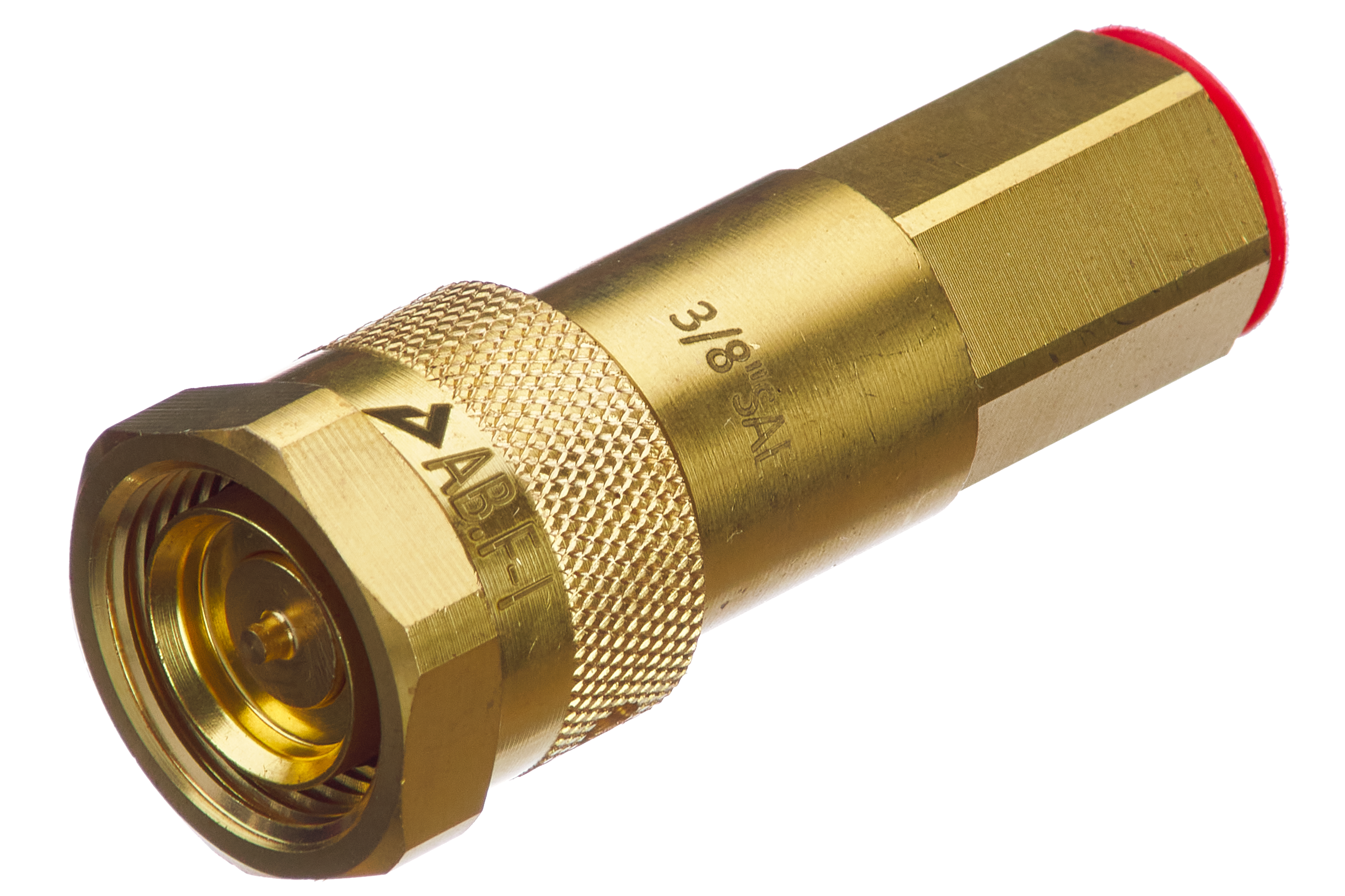
Many systems rely on modular flexibility. Operators constantly attach and detach transfer hoses. Utilizing a quick coupling for pipe introduces significant mechanical wear. Threads grind against each other daily. Internal seals compress and expand repeatedly. This manual handling actively reduces the effective structural boundaries at the connection site. You must specify highly robust dimensions to safely handle this continuous coupling stress.
HVAC applications present unique localized challenges. Commercial systems endure relentless mechanical shaking. Continuous compressor vibration travels straight down the lines. Using an air conditioner connecting pipe kit requires strict attention to fatigue limits. Micro-friction occurs at support brackets. The metal literally rubs away over thousands of hours. Precise dimensional thickness prevents microscopic cracks. Preventing cracks stops hazardous refrigerant leaks entirely.
Opting for thinner schedules initially looks attractive on paper. However, under-specifying invites immediate disaster. The base dimensions cannot handle normal daily wear rates. You face premature structural failures within months. Emergency maintenance crews must scramble constantly. Toxic or scalding fluids easily breach the compromised boundaries. This presents massive safety hazards to your floor personnel. The resulting downtime destroys production schedules entirely.
Conversely, throwing the thickest possible schedule at a problem damages project ROI. Thicker dimensions increase overall system weight dramatically. You must install heavily reinforced hanger supports to carry the extra burden. Welding processes become overly complicated. Welders spend significantly more hours completing a single joint. They require specialized filler materials. Heavy over-specifying drives up initial capital expenditure needlessly.
Guesswork has no place in modern maintenance strategies. You must implement baseline Ultrasonic Thickness (UT) gauging programs. Technicians use advanced sound waves to measure remaining metal layers accurately. This non-destructive testing tracks actual daily wear strictly against your theoretical calculations. Regular UT scans reveal hidden thinning before catastrophic ruptures occur. It transitions your strategy from reactive panic to planned predictability.
Baseline UT Gauging Best Practices
| Inspection Phase | Recommended Action | Frequency |
|---|---|---|
| Initial Installation | Capture baseline thickness measurements | Once at startup |
| High-Risk Zones | Scan elbows, tees, and couplings | Bi-annually |
| Straight Runs | Scan standard horizontal sections | Annually |
Procurement teams must demand complete transparency. A credible pipe wall thickness supplier must provide exact metallurgical data. You need documented proof of dimensional consistency across the entire production batch. Mill Test Reports (MTRs) verify the exact chemical composition. They confirm the physical yield strengths. Never accept materials lacking full traceability. Untraceable steel often hides dangerous manufacturing flaws.
Manufacturing is never perfectly exact. Acceptable deviations exist within global standards. However, lenient manufacturing tolerances severely impact high-wear applications. Some ASTM standards allow a +/- 12.5% deviation in thickness. A nominal 10mm specification might legally arrive at 8.75mm. You lose a massive portion of your expected lifespan on day one. Evaluate vendors strictly based on their ability to hold tight manufacturing tolerances.
Do not partner with simple catalog vendors. You need strategic engineering advice. Look for suppliers offering deep application-specific consultation. They should advise on the exact metallurgical requirements for harsh environments. For instance, they must guide you on specifying dimensions for a high-vibration cooling setup. Their engineering team should actively help you refine your internal standards for long-term survival.
Daily industrial use guarantees continuous material degradation. Fluids erode metal, temperatures cause fatigue, and pressures test physical limits. Your primary goal is achieving managed, predictable performance through accurate engineering specification. Ignoring these realities leads to dangerous ruptures and expensive downtime.
Take immediate action today. Urge your maintenance teams to audit current failure rates across the facility. Recalculate your required corrosion allowances using actual historical data. Finally, initiate a stringent quality assurance review with your prospective or current vendors to ensure lasting system integrity.
A: Start with the baseline required thickness for containing internal pressure. Determine your historical local corrosion rate in millimeters per year. Multiply this annual rate by the expected lifespan of the system. Add this final number to your baseline thickness. This standard engineering framework provides a safe, reliable buffer against continuous daily degradation.
A: A higher Schedule provides a thicker physical boundary and higher pressure capacity. However, it does not guarantee better performance alone. Performance depends heavily on material grade and environmental compatibility. An overly thick schedule of the wrong alloy will still corrode rapidly. You must match the specific metallurgical grade to the chemical environment first.
A: Couplings endure extreme localized stress. Frequent manual handling physically wears down the external components. Flow turbulence sharply increases exactly at the joint interface. Furthermore, cutting threads naturally reduces the effective structural thickness at the connection site. This combination of mechanical stress and reduced mass makes couplings highly vulnerable to early failure.
A: Industrial HVAC commonly utilizes ASTM B280 standards for ACR copper tube. These standards dictate specific dimensions based on system pressure requirements. However, nominal standards only provide a baseline. Your final thickness must firmly account for continuous operational vibration from heavy compressors. Always add a fatigue allowance to prevent refrigerant leaks over time.


